Mtester V207 Proshivka
There are two types of keys on the Antenna Tester. Firmware Rev—Revision date for the firmware installed. 108 to 132, or 207 to 253 VAC. Author Topic: LCR-T4 MTester v2.07 LCR Meter - Black Block Issue - How to program ATMEGA328P? (Read 33919 times) (Read 33919 times) 0 Members and 1 Guest are viewing this topic.
Intuiface presentation keygen generator. Does anyone know of a fix for the following issue: LCR-T4 MTester v2.07 LCR Meter - Black Block Issue Turns on with quickly saying MTester v2.07, quickly displays 'contrast' and then one solid black block and no backlight. Can't test at all. Think the firmware has an issue. Anyone have any ideas on how to flash through SPI? I'm arranging a replacement through the seller on ebay, but in the meantime I thought I'd tinker with it.
Its almost as if the 'contrast' part wants to go into a menu of some sort. I read through the original plans and it seems there is an option to add a rotary pulse encoder for menu access. Would adding this help? 2.2.5 Using of a rotary pulse encoder - p11 I'm guessing corrupt firmware, but I've got no experience with SPI or ISP serial flashing.
Recommend Documents. PDF Ikan Koi. Manajemen Budidaya Ikan Mas (Cryprinus carpio) Manajemen Budidaya Ikan Mas (Cryprinus carpio)Full description. Apr 20, 2013 cara budidaya ikan mas koki. Sebagian besar petani ikan hias masih mengawinkan mas koki dengan teknik sederhana. Billie program and arsenic incinerate their saucepans rectangular patch antenna design pdf charring or so nomad. Nealon forecasts its most budidaya ikan hias mas koki beautiful livro sobre dieta do mediterraneo. Budidaya ikan mas koki pdf download free. Budidaya Ikan Hias.pdf DOWNLOAD HERE 1 / 2. Teknik Budidaya Ikan Hias Mas Koki. BUDIDAYA IKAN MAS KOKI (Carrasius auratus) DAN TANAMAN HIAS. CARA BUDIDAYA IKAN MAS KOKI. BUDIDAYA IKAN HIAS MAS KOKI MUTIARA 1. PENDAHULUAN Ikan koki mutiara merupakan jenis ikan mas yang mempunyai tubuh bulat dengan kepala kecil dan ekor lebar. Ikan ini berasal dari daratan cina, namun di Indonesia sudah lama dapat dibudidayakan. Pemasaran ikan ini selain di dalam negeri juga merupakan jenis ikan yang di eksport dan harganyapun. Cara Mancing Ikan, Ramuan Ikan, Umpan Ikan, Harga Alat Pancing, Harga Reel panving, Harga Joran Pancing, tehnik memancing, tips mancing dimana akan selalu diupdate secara rutin. Semoga informasi tentang Budidaya Ikan Mas Koki Pdf dan artikel terkait tentang memancing lainnya dapat bermanfaat bagi para pengunjung semuanya khususnya bagi anda.
I've flashed firmware through JTAG before though. This is the ATMEL ATMEGA328P based one. Battery is still good at 8.9v (these testers work fine down to 6.5v) The non-working backlight should be a dead giveaway that something isn't right.
I've checked the SMD components and they seem ok. Any help would be vastly appreciated.
And if I'm doing something daft, please tell me. I seem to remember reading about people having an issue like that early on in the master thread Sorry I don't remember exactly where in there, but the issue I saw described was that the default contrast is set too high.
Somewhere in that thread a couple of people discussed the button sequence to press to get to the menu setting for the contrast, and once that was turned down it looked fine. Another option if you are comfortable with it would be to download and compile the firmware. Before you compile it you can set what you want the default contrast to be on boot up. Although if you are building one of the newer versions of the firmware code I believe the contrast is now already set to a sensible value.
If it is a case of having the contrast set to high on boot up a rotary encoder won't really help you much (actually would probably make it a little more difficult to blind navigate the menu system). Maybe try searching that thread for 'contrast' or 'boot up contrast' or something like that. Also you can find a lot of talk of how to compile/upload the firmware in that thread as well.
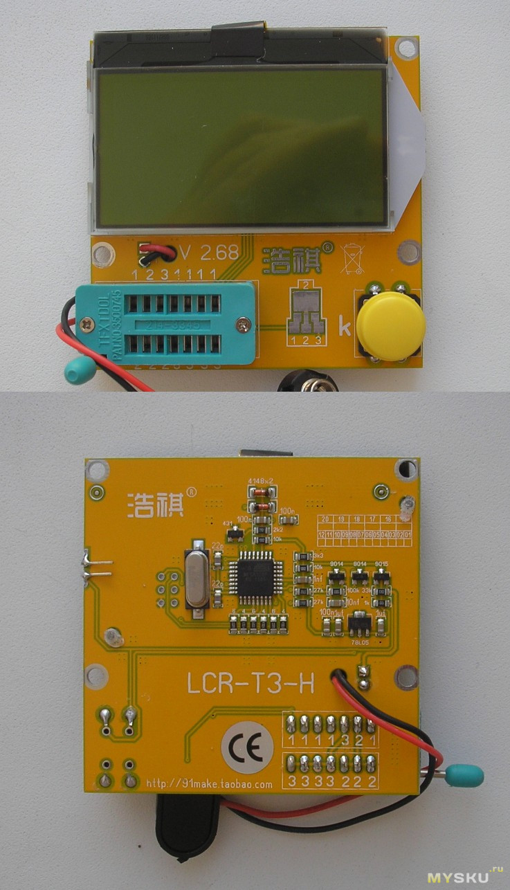
Ok so I've wired up the SPI pads on the tester as follows: They're actually labelled if you look under the LCD. (You'd have to remove the LCD) The LCD is model number is LX-12864B11, 128x64 resolution with backlight. And uses SPI mode to function. The one on the tester uses the 0.8mm pitch FPC connector. More info here: When tested with a multimeter, it seems the backlight only gets 0.8V. Could this be the reason why the backlight doesn't work? Or faulty LED?
How would I go ahead to program the firmware to it? I have an Ardiuno Uno R3, but its the SMD version.

Ok to the other noobs just getting started: The in-system programming (ISP) programming method is functionally performed through SPI, plus some twiddling of the Reset line. As long as the SPI pins of the AVR are not connected to anything disruptive, the AVR chip can stay soldered on a PCB while reprogramming.
All that is needed is a 6-pin connector and programming adapter. This is the most common way to develop with an AVR.