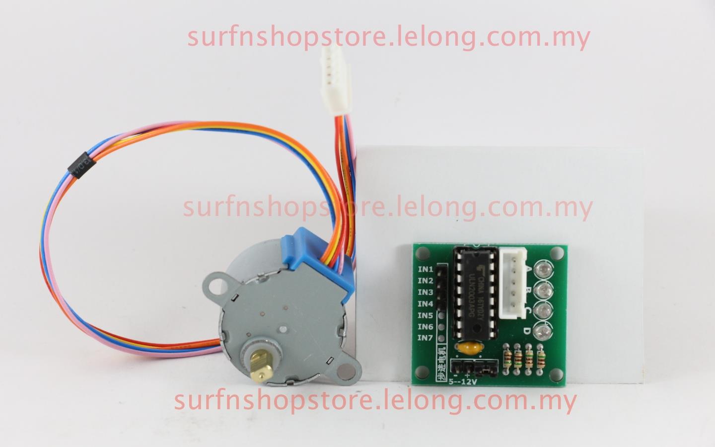
5 Phase Stepper Motor Driver Projects

Stepper motors as the name depicts moves in steps. They are popular in industry due to their ability to rotate their shaft at an accurate location and outputting high torque at low angel movements. One can also control the stepper motor step speed and angle accurately with out the need of feed back mechanism. Though they consume high power and their software settings are not easy to understand but once learnt deeply and properly will vanish all the stereotypes about them.
Feb 06, 2017 I have 5 4-Phase 5-Wire Stepper Motor with ULN2003 Driver Board. I connected these directly to the arduino mega. Im trying to move them simultaneously but to different angles. Althought atm, i just need to know if the circuit or code are remotely similar to what id need for that to happen.
Craagle serials. In this case you can use alternative, free software or you can download a pirated, cracked version of the program.
Stepper motors are dc motors which takes steps and moves its shaft when digital pulses are supplied across its pins. Stepper motors are used in precision requirement operations such as robotic arms, 3D printers, scanners, disc rota-tors and cnc machines. Stepper motors are brush less dc motors. They have coils and permanent magnets which rotate the shaft.There are generally two types of stepper motors categorized on their coil configurations uni polar and bi polar.

Uni polar motors have a common signal wire whose signal remains fixed all the time. Bipolar motors are independent from common wire. I am not going to dive deep in the stepper motors difference. Just wrote above the major difference between the two stepper motors. Stepper motors sink 1 ampere of current during normal operation. So we need a power supply which can source 1 ampere of continuous current.
The old technique is build a H-bridge circuit using transistors or mosfets which can provide sufficient amount of power and can drive motors easily. Making H-bridge circuit is time consuming and takes lot of effort. Luckily now a days their are pre assembled H-bridge drivers available in market which are not only cheap but are also very easy to control.
So i decided to use a pre assembled H-bridge circuit in this project. A4988 bipolar stepper motor driver is best suited for our project. A4988 can source 1 amperes to 2 amperes of continuous current at voltages from 8 to 35 volts.
It requires 3 to 5 volts for its operation. Pin out and equivalent circuit of the product is below. Apply 3 to 5 volts across VDD and Gnd pins of A4988 motor driver. 1A, 1B, 2A and 2B are output pins.
These pins must be correctly connected to 2 phases of bipolar stepper motor. VMOT and GND are power pins connect your power source with them. You can supply 8 to 35 volts across VMOT and GND.